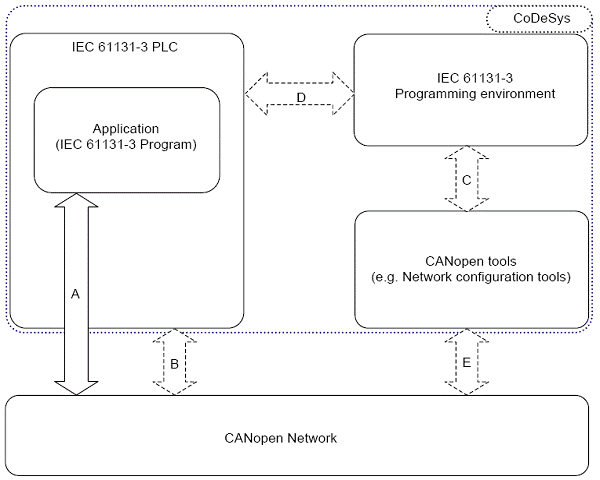
This specification uses the standardized CANopen interface for IEC 61131-3 programmable devices such as PLC.
The devices use communication techniques which conform to those described in the CiA Draft Standard DS-301 (Application Layer and Communication Profile), Draft Standard Proposal DSP-302 (Framework for Programmable CANopen Devices), and Draft Standard Proposal DS-405 (Interface and Device Profile for IEC 61131-3 Programmable Devices). These documents should be consulted in parallel to this specification.
- /DS-301/ CiA Draft Standard DS 301 V4.02 CANopen Application Layer and Communication Profile
/DSP-302/ CiA Draft Standard Proposal DSP 302 V3.1 CANopen Framework for Programmable CANopen Devices
/DS-405/ CiA Draft Standard Proposal DS 405 V2.0 CANopen interface and Device Profile for IEC 61131-3 Programmable Devices
In general, generating an application implements the handling of up to five interfaces:
Generating an application /handling interfaces

This description covers only the interface:
Therefore, the access to a CANopen communication system from within an IEC 61131-3 program is based on calls to function blocks
This descricption does not (yet) cover the interfaces:
Utility functions for debugging, monitoring and network management
Interface between CANopen tools and IEC 61131-3 programming environment
Manufacturer specific interface between programming environment and PLC runtime
CANopen tool specific interface between configuration tool and network
Notice
The figure does not necessarily describe the use of different tools for programming and configuration. One tool can handle both functionalities and hide the interfaces. An example is given by the programming tool CODESYS (see dotted line), where the CANopen configuration and the runtime software on the PLC is included.
Application interface
Every application within an IEC 61131-3 level must be able to write to (SDO) or read a node connected to CANopen in a device object directory. Further elements of a CANopen communication are Process Data Objects (PDO) which are supported in the process image within the IEC application as inputs (Receive PDO; i.e.: %IX.. ) or outputs (Send PDO; i.e.: %QW.. ). Received asynchronous error messages (EMCY) are registered for each node in a buffer. The network status is controlled by the Network management (NMT). With CANopen, a node guarding functionality is available, and synchronized communication for process data is possible.
The chapters of the current description outline the requirements to a function block library for CANopen communication.